Arduino arcade joystick controller
/We have a saying at Cuddleburrito. Build it. It's for when the only thing available just isn't good enough for what you're trying to do. It's something you yell down the aisle of Home Depot when they're missing the tool you need. After fiddling with way too many button encoders that didn't do exactly what we wanted, it was time for BUILD IT!
In the case of the GameThing button encoder, the concept and heavy lifting have already been done for us so this blog post focuses on the improvements made to existing electronics and code, namely the Arduino firmware. Google searches produced many tutorials on hard coding the buttons into the firmware ( e.g. one and two ), but we had trouble finding examples that could input an arbitrary number of buttons, so this is what we aimed to improve. Click below to jump straight to our GitHub project repository. Keep reading to see how we debounce an arbitrary amount of input pins ( 16 in our case ) using loops and arrays.
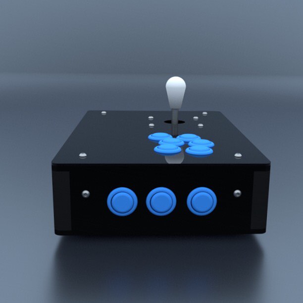
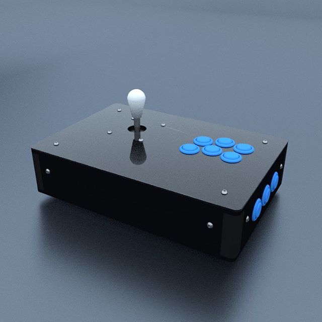
Some of the button encoders we've tested, our newest Arduino powered one on the far right.
The whole design hinges on the fact that the Arduino can be easily setup as a USB Human Interface Device. USB HID is a way for computers to communicate with peripherals like mice, keyboards, and joysticks on the USB port. For our application, we wanted our arcade controller to be recognized as a keyboard, which means each button and joystick direction would be mapped to a keyboard key. The Arduino microcontroller's job would be to check if an arcade button is pressed and send the corresponding keyboard character to the computer. Thus, any game/software that uses your computer's keyboard will work out of the box.
Hardware
- Arduino. We used a Pro-Micro model but this code should run on any Arduino provided you use the same pins. (Note: the Pro-Micro has some programming quirks, check your Arduino's documentation)
- Buttons/Joystick
Software
- Bounce2 Library
- Arduino SDK
- Arduino Addon File (for Pro Micro, more info at: SparkFun)
Wiring
the ground connection (yellow wire) daisy-chains the buttons together to simplify the wiring further. Note the wires were unplugged from the controller to take the photo.
By taking advantage of the Arduino's pull-up resistors we can make the wiring much easier to put together. Connect one of the button's leads to an open microcontroller pin, and the other button lead to the microcontroller's ground pin. In the firmware code, setup each of the Arduino's pins to use the internal pull-up (e.g. pin nine below but you need to do this for each pin) with:
pinMode( 9, INPUT_PULLUP );
The internal pull-up resistor is a convenient feature of microcontrollers that helps reduce part count and circuit complexity. Pull-up resistors hold a microcontroller's pin in a steady HIGH state, compared to a "floating" state, which would be unpredictably either HIGH or LOW since the pin wasn't connected to anything. When the button is pressed it connects the pin to ground which immediately causes the pin to now sense LOW. This state change from HIGH to LOW and back can be read by the micrcontroller which then sends the appropriate keypress to the computer.
Firmware and debounce strategies
The microcontroller has a simple job: detect if the microcontroller pin has gone LOW ( i.e. the arcade button has been pressed ), but because mechanical systems vibrate the firmware has to be a little more complex to account for this. For a very brief period of time after the metal contacts first touch inside the button, they vibrate from the impact and cause the microcontroller to sense a flurry of HIGH and LOW signals. This is problematic because the computer would interpret it as multiple button presses instead of just one. Mitigation strategies for false button presses like these are called debouncing. The Arduino code we wrote incorporates two debouncing strategies that can be used individually or in parallel by changing a couple constants in the code. The first is the Bounce2 library and the second is a counting algorithm.
The Bounce2 library debounces by checking the buttons state after a set amount of time. This effectively ignores the erroneous signals in the button mechanism. Only after a set amount of time has passed will the code confirm that the button state is still changed and send the computer the keypress signal.

A common debounce strategy is waiting a certain amount of time after the transition to confirm that the button state is still true. The unstable interval occurs in both transitions from high-low and low-high. photo Source: https://github.com/thomasfredericks/Bounce2/wiki
The second debounce strategy is a counting algorithm that waits for a set number to be reached. The algorithm increments a value by one if the pin is HIGH and decrements by one if LOW as fast as it possibly can. The Arduino updates a value for each button sequentially, repeats this infinitely, and when the value reaches a defined limit, the micrcontroller tells the computer the button has been pressed. Unlike the Bounce2 library, which depends on a fixed time delay, the counting algorithm, in theory, should outperform the fixed time delay because it counts the spurious HIGHs and LOWs of the mechanical vibration rather than wait for a fixed amount of time. However, this all depends on the wait time set for the Bounce2 code and the limit value in the counting algorithm. A future post will explore the effects of changing these two constants.
Configuration
The code provided on GitHub has four settings that can be tweaked to change button mappings and controller performance:
- buttonPins[ ] - Defines which pins correspond to which button
- buttonPresets[ ] - Defines the keyboard keys per button, listed in the same order as buttonPins[ ]
- BOUNCE_WAIT - Bounce2 library's setting for time to wait for a stable button signal
- BOUNCE_COUNT - Counter algorithm's limit for triggering button press
One thing to keep in mind, is that it takes a certain amount of time to execute one loop of the firmware code, which gives time for the button to settle, and act like a debounce function. For our code that checks 16 button states, the default settings of 10 and 1 for BOUNCE_WAIT and BOUNCE_COUNT respectfully, were adequate. If you reduce the number of button checks, these settings may need to be increased to compensate.
Conclusion and next steps
We're confident that these open-source Arduino button encoders are a great start to endless customizations and innovative features for DIY arcade controllers. Best of all we can help each other while doing it. In the near future, we want to further test these debounce methods and quantify button to photon lag. Using what we learn we hope to build button controllers sought after for tournament players. Moreover, LED animations, multiple button presets, console support, and much more could be implemented. Let's share our knowledge with each other!